ICND1 – Basic Questions

ICND1 – Basic Questions

Question 1
Explanation
CSMA/CD stands for Carrier Sense Multiple Access with Collision Detection. In an Ethernet LAN, before transmitting, a computer first listens to the network media. If the media is idle, the computer sends its data. If the media is not idle (another station is talking), the computer must wait for some time.
When a station transmits, the signal is referred to as a carrier. Carrier Sense means that before a station can send data onto an Ethernet wire, it have to listen to see if another “carrier” (of another station) is present. If another station is talking, this station will wait until there is no carrier present.
Multiple Access means that stations can access the network at any time. It is opposed to Token-Ring network where a station must have the “token” so that it can send data.
Although Carrier Sense help two stations not send data at the same time but sometimes two stations still send data at the same time! This is because two stations listen for network traffic, hear none, and transmit simultaneously -> a collision occurs and both stations must retransmit at some later time.Collision Detection is the ability of the media to detect collisions to know that they must retransmit.
Basically, the CSMA/CD algorithm can be summarized as follows:
+ A device that wants to send a frame must wait until the LAN is silent (no one is “talking”)
+ If a collision still occurs, the devices that caused the collision wait a random amount of time and then try to send data again.
Note: A switch separates each station into its own collision domain. It means that station can send data without worrying its data is collided with the data of other stations. It is as opposed to a hub which can cause collision between stations connected to it.
Question 2
Explanation
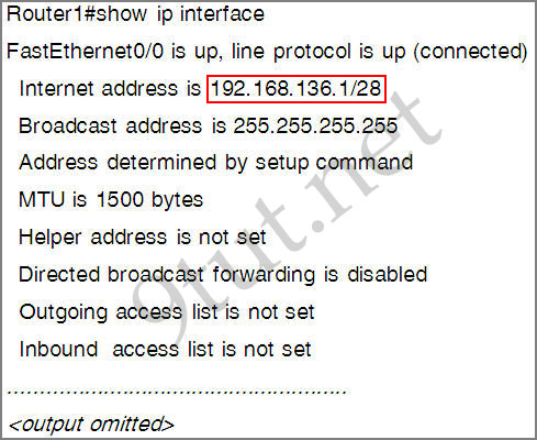
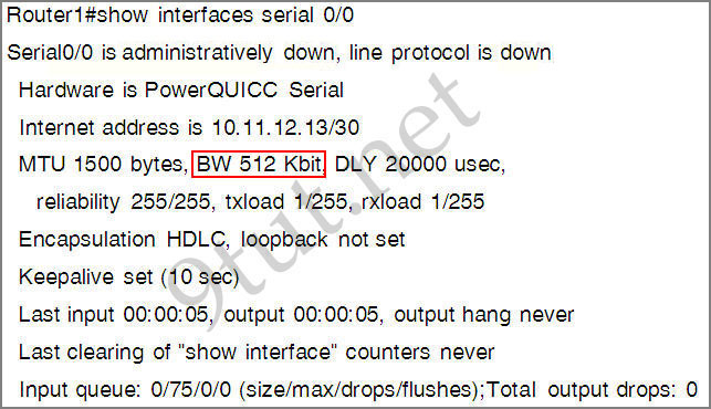
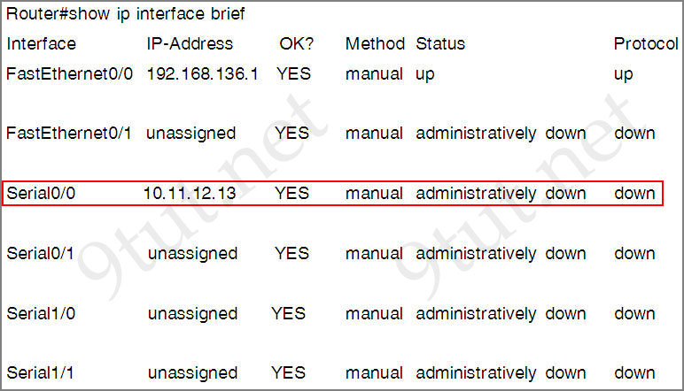
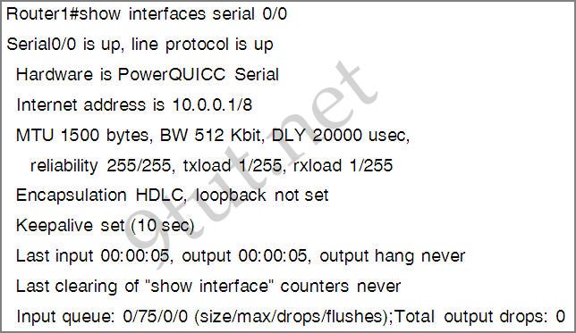
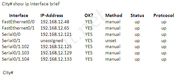
Only two commands “show interfaces” and “show ip interface brief” reveal the status of router interfaces (up/up, for example).
The outputs of two commands are shown below:
show_config_question_answer_2.jpg
show_ip_interface_brief.jpg
Question 3
Explanation
HTTP is based on TCP connection so a TCP connection must be established first between the workstation and the web server.
Question 4
Explanation
Hubs do not separate collision domains so if hub is used in the topology above, we will have only 1 collision domain. Switches do separate collision domains so if hubs are replaced by switches, we would have 22 collision domains (19 collision domains for hosts and 3 collision domains among three switches. Please notice that the WAN (serial) connection is not counted as a collision (or broadcast) domain.
Question 5
Explanation
A broadcast storm can cause congestion within a network. For more information about broadcast storm please read my STP tutorial.
Question 6
Explanation
Before a host can send ICMP (ping) packets to another device, it needs to learn the MAC address of the destination device so it first sends out an ARP Request. In fact, the first ping packet is dropped because the router cannot create a complete packet without learning the destination MAC address.
Question 7
Explanation
The “show running-config” command displays active configuration in memory.
Question 8
Question 9
Question 10
Explanation
Full-duplex communication allows both sending and receiving of data simultaneously. Switches provide full-duplex communication capability. Half-duplex communication only allows data transmission in only one direction at a time (either sending or receiving).
Security Testlet

Security Testlet

Question


Security_SIM.jpg
Not sure about the requirement of this question but it is something like this:
Before this switch and router can be put to use in the network, what security risks can be found…
We are still not sure about the configurations in this sim but we got some information to share with you (updated on December-07-2011. Thanks Joe Mendolaxallax and many candidates who share the information!):
Maybe this is the configurations on Router and Switch (but notice that they are surely missing something):
ROUTER A CONFIGURATION
!
no service password-encryption
!
enable password cisco
!
username ciscouser privilege 15 password 0 cisco
!
banner motd ^CWelcome! If you encountered any problem, please consult the administrator^C
!
line vty 0 4
password 4t&34rkf
login local
transport input telnet ssh
!

SWITCH A CONFIGURATION
!
!
no service password-encryption
!
hostname switch1
enable password cisco
username ciscouser password 0 cisco
ip domain-name cisco.com
banner login ^c
************ welcome to Switch1. If you encountered any problem, please consult the administrator ************* ^c
line con 0
line vty 0 4
login login local
transport input ssh
line vty 5 15
login local
transport input ssh
Note: This is just what we gather and guess. In the exam the configurations may be different so make sure you understand about “enable secret”, “enable password”, “login”, “login local”, “transport input”, “line vty”, “service password-encryption”, “bannder motd”, “privilege” before taking this exam!
This sim has 4 questions:
Question 1
Guideline to answer this question:
Because the “service password-encryption” is not set on RouterA so the password to access privileged mode (via the command “enable password cisco”) is unencrypted. Also, the password for VTY is unencrypted (notice that the password “4t&34rkf” is in fact unencrypted) -> A is correct.
Although the banner says “Welcome …” but it does not leak any security information so it is still safe -> B is not correct.
From the command “transport input telnet ssh” we learn that remote access can be mad through telnet or SSH. This is also the default setting of Cisco router -> C is correct.
In the “line vty 0 4″ configuration, the type of login is specified as “login local”. It means that the router will not use the password configured under “line vty 0 4″ (in this case “4t&34rkf”) but it will use the user & password configured in “username ciscouser privilege 15 password cisco” command. The command “username ciscouser privilege 15 password cisco” will grant the privilege of 15 for “ciscouser” user -> D is correct.
Question 2
Guideline to answer this question:
A is correct as we can telnet from line 0 to line 4 (line vty o 4).
We can use both telnet and SSH to connect to this router (transport input telnet ssh) -> B is not correct.
C is correct as we can telnet to it.
D is not correct because by default, the timeout is set to 10 minutes on both the console and the vty ports.
E is not correct as NAT can be used even DHCP is not used.
Question 3
Guideline to answer this question:
Privilege mode on RouterA is protected with unencrypted password (via “enable password” command) -> A is correct.
B is not correct as mentioned above.
The password of VTY lines is “4t&34rkf”. Although it is unencrypted but it is not a weak password because it has number & special characters inside -> C is not correct.
Although a password of “4t&34rkf” is configured but with the command “login local”, router will use the username of “ciscouser” & password of “cisco” (configured in “username ciscouser privilege 15 password 0 cisco” command) -> D is correct.
By checking the configuration of routerA with the “show run” command. To support web server access it must have the command “ip http server” but it does not -> E is not correct.
Question 4
Guideline to answer this question:
We haven’t had enough information about switch configuration so we can’t be sure about the correct answers but the below is a guideline:
Answer B is surely not correct as the wording in banner does not leak any security information.
If under “line vty 0 4″ you see the “login” command but it does not have a password then maybe answer C is correct. In this case if we try to telnet/ssh to the switch then we will receive a message “Password required, but none set” then we are kicked out ^^.
If you see popular username and password then maybe answer D is correct.
If the command “transport input …” specifies “telnet” as a method then answer E is correct.
For answer F, if you see something like this:
line vty 0 4
privilege level 15
or these lines:
username ciscouser privilege 15 password cisco
and
login local (in “line vty 0 4″)
then answer F is correct.
———————————-
Hope you will contribute your experience about this sim after taking the ICND1 exam. We will post here when we get new information about this sim as soon as possible.
RIPv2 SIM

RIPv2 SIM

Question
Configuration_Sim.jpg
TUT Company recently installed a new router in their office. Complete the network installation by performing the initial router configurations and configuring RIPv2 routing using the router command line interface (CLI) on the R2-TUT.
Name of the router is R2-TUT
Enable-secret password is Sec@ret
The password to access user EXEC mode using the console is Sec@ret2
The password to allow telnet access to the router is Sec@ret3
IPV4 addresses must be configured as follows:
Ethernet network 213.123.20.128/27 – router has last assignable host address in subnet
Serial network is 200.0.1.16/28 – router has last assignable host address in the subnet. Interfaces should be enabled.
Router protocol is RIPv2
Answer and Explanation
1) Name the router:
Router>enable
Router#configure terminal
Router(config)#hostname R2-TUT
2) Set secret password:
R2-TUT(config)# enable secret Sec@ret
3) Set password for the console:
R2-TUT(config)#line console 0
R2-TUT(config-line)#password Sec@ret2
R2-TUT(config-line)#login
R2-TUT(config-line)#exit
4) Set the Telnet password:
R2-TUT(config)#line vty 0 4
R2-TUT(config-line)#password Sec@ret3
R2-TUT(config-line)#login
R2-TUT(config-line)#exit
5) Assign IP address for Ethernet interface (Fa0/0):
The Ethernet network 213.123.20.128/27 has:
Increment:32 (/27 = 255.255.255.224 or 1111 1111.1111 1111.1111 1111.1110 0000)
Network address: 213.123.20.128
Broadcast address: 213.123.20.159 (because 128 + 32 – 1 = 159)
Therefore the last assignable host address in this subnet is 213.123.20.158 and we will assign it to Fa0/0 interface with these commands:
R2-TUT(config)# interface fa0/0
R2-TUT(config-if)#ip address 213.123.20.158 255.255.255.224
R2-TUT(config-if)#no shutdown
R2-TUT(config-if)#exit
6) Assign IP address for Serial interface (S0/0):
Serial network 200.0.1.16/28 has:
Increment:16 (/28 = 255.255.255.240 or 1111 1111.1111 1111.1111 1111.1111 0000)
Network address: 200.0.1.16
Broadcast address
: 200.0.1.31 (because 16 + 16 – 1 = 31)
So the last assignable host address in this subnet is 200.0.1.30. Finally we assign it to s0/0/0 interface:
R2-TUT(config)# interface s0/0/0
R2-TUT(config-if)#ip address 200.0.1.30 255.255.255.240
R2-TUT(config-if)#no shutdown
R2-TUT(config-if)#exit
7) Configure RIP v2 routing protocol:
R2-TUT(config)#router rip
R2-TUT(config-router)#version 2
R2-TUT(config-router)#network 213.123.20.0
R2-TUT(config-router)#network 200.0.1.0
R2-TUT(config-router)#end
R2-TUT#copy running-config startup-config
Note: We should use classful networks (213.123.20.0 & 200.0.1.0) when configuring RIP. If we use detailed networks (213.123.20.128 & 200.0.1.16) the router will automatically convert them into classful networks.
Show Configuration Sim

Show Configuration Sim

This task requires the use of various show commands from the CLI of Router1 to answer 5 multiple-choice questions. This does not require any configuration.
Show_Configuration_Sim_topology.jpg
NOTE: The show running-configuration and the show startup-configuration commands have been disabled in this simulation.
To access the multiple-choice questions, click on the numbered boxes on the right of the top panel.
There are 5 multiple-choice questions with this task. Be sure to answer all 5 questions before leaving this item.
Question 1
What is the broadcast address of the subnet of the LAN connected to Router1?
A – 192.168.136.15
B -192.168.136.31
C -192.168.136.63
D – 192.168.136.127
E – 255.255.255.255
Answer: A
Explanation
The “show running-configuration” and “show startup-configuration” have been disabled as stated above so we should use the show ip interface command to get information about the LAN network connected to Router1.
show_config_question_answer_1
From the output we learn that the ip address of the FastEthernet interface of Router1 is 192.168.136.1 and the subnet mask is /28. Therefore:
Increment: 16 (/28=1111 1111.1111 1111.1111 1111.1111 0000)
Network address: 192.168.136.0
Broadcast address: 192.168.136.15 (15 = 0 + 16 – 1)
-> The broadcast address of this subnetwork is 192.168.136.15
Question 2
What is the bandwidth on the WAN interface of Router1?
A – 16 Kbit/sec
B – 32 Kbit/sec
C – 64 Kbit/sec
D – 128 Kbit/sec
E – 512 Kbit/sec
F – 1544 Kbit/sec
Answer: E
Explanation
To find out the bandwidth on the WAN (serial) interface of Router1 we need to use the show interfaces serial 0/0 command:
show_config_question_answer_2
Therefore the bandwidth on the WAN is 512 Kbit/sec.
Question 3
What interfaces on Router1 have not had any configurations applied? (Choose two)
A – Ethernet 0
B – FastEthenet 0/0
C – FastEthernet 0/1
D – Serial 0
E – Serial 0/0
F – Serial 0/1
Answer: C F
Explanation
Use the show ip interface brief to identify what interfaces Router 1 have. Notice that Router1 does not have Ethernet 0 and Serial 0 interfaces. FastEthernet 0/0 and Serial 0/0 were configured with their IP addresses therefore only FastEthernet 0/1 and Serial0/1 have not had any configurations applied.
Question 4
Including the address on the Router1 FastEthernet interface, how many hosts can have IP addresses on the LAN to which Router1 is connected?
A – 6
B – 14
C – 62
D – 128
Answer: B
Explanation
The mask address of interface Fa0/0 of Router1 is /28 (as shown in question 1), which has four 0 bits (1111 1111.1111 1111.1111 1111.1111 0000). Therefore there are 24 – 2 = 14 assignable IP addresses for hosts on the LAN.
Question 5
The hosts in the LAN are not able to connect to the Internet. Which commands will correct this issue?
A – Router1(conf)# interface fa0/0
Router1(conf-if)# no shutdown
B – Routed (conf)# interface fa0/1
Router1(conf-if)# no shutdown
C – Router1(conf)# interface s0/0
Router1(conf-if)# no shutdown
D – Router1(conf)# interface s0/1
Router1(conf-if)# no shutdown
E – Router1(conf)# interface s0/0
Router1(conf-if)# ip address 10.11.12.13 255.255.255.252
F – Router1(conf)# interface s0/1
Routerl (conf-if)# ip address 10.11.12.13 255.255.255.252

Answer: C
Explanation
We should check the statuses of all the interfaces on Router1 with the show ip interface brief command:
show_config_question_answer_4
From the output, we learn that the status of Serial0/0 interface which connects to ISP router is currently “administratively down”. This status indicates this interface is shutting down so we need to turn it on.

ICND1 100-101 and ICND2 200-101

ICND1 100-101 and ICND2 200-101